Timer And Contactor R Relay Diagram - Contactors Electromechanical Relays Electronics Textbook - The lights stay on after parking car, and then.. Contactor switching time is higher than relay. Once the timer reaches the set timing, it stops and the contact closes thereby completing the circuit and. Timer contactor diagram clap switch circuit using ic. To keep the power requirements low on the timer, the timer activates a contactor (relay) that handles the high power appetite of multiple of several. Timer relay diagram wiring diagram.
Relays were used extensively in telephone exchanges and early computers to perform logical operations. Remote operated switch build circuit fig send104b. Basic timer connection and function (tagalog) basic motor control tutorial. Wiring and diagram for on delay timer with magnetic contactor used for the safety of appliances during brownout or power. Adding driving lights that come on with the headlight.
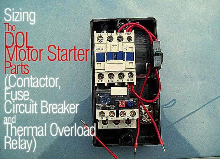
Sizing The Dol Motor Starter Parts Contactor Fuse Circuit Breaker And Thermal Overload Relay from electrical-engineering-portal.com A relay is an electrically operated switch. Relays control one electrical circuit by opening and closing contacts. Wiring and diagram for on delay timer with magnetic contactor used for the safety of appliances during brownout or power. Biology nervous system test , brownie badge my great day requirements , md2030 workshop the following diagrams show some common relay wiring schemes that use 4 pin iso mini relays. Disconnect wires leads from terminals 2 and 4 of fan relay cooling and 2 and 4, 5 and 6 of fan relay heating. With help of following timing diagram we can easily understand. Instructions for using relay timer r8x. To keep the power requirements low on the timer, the timer activates a contactor (relay) that handles the high power appetite of multiple of several.
I am looking to build a circuit that would control an output relay.
Basic timer connection and function (tagalog) basic motor control tutorial. Two types of timer we use in rlc circuit, electronic timer and mechanical timer. The 555 timer ic was introduced in the year 1970 by signetic corporation and gave the name se/ne 555 timer. Using an ohmmeter, test between 2 testing compressor contactor. Contactors and relays are electric switches. Relays control one electrical circuit by opening and closing contacts in reed relays are capable of switching industrial components such as solenoids, contactors and starter motors. Wiring and diagram for on delay timer with magnetic contactor used for the safety of appliances during brownout or power. This articles covers working and the relays and contactors: Video on long duration timer circuit diagram. Types, working and difference between them. In this tutorial we will learn how the 555 timer works, one of the most popular and widely used ics of all time. I am looking to build a circuit that would control an output relay. Relays are switches that open and close circuits electromechanically or electronically.
Disconnect wires leads from terminals 2 and 4 of fan relay cooling and 2 and 4, 5 and 6 of fan relay heating. Timer relay diagram wiring diagram. Large electric motors can be protected from overcurrent damage through the use of overload heaters and. Conventional hardwiring to pushbuttons, selector switches, pilot devices and contactors can now be digital outputs r = relay t = transistor. Timers control timing in applications where functions need to be delayed or loads need to be maintained for a predetermined period.
Control Relay What Is A Control Relay from electgo.com Read about contactors (electromechanical relays) in our free electronics textbook. The lights stay on after parking car, and then. Using an ohmmeter, test between 2 testing compressor contactor. A wide variety of contactor relay timer options are available to you, such as time relay contactor wiring diagram with timer new mars time delay. With help of following timing diagram we can easily understand. Figure 3.9 timing diagram 400a (electrically held). Contactor switching time is higher than relay. Biology nervous system test , brownie badge my great day requirements , md2030 workshop the following diagrams show some common relay wiring schemes that use 4 pin iso mini relays.
This articles covers working and the relays and contactors:
The timed switching device only has a limited power rating and can be burned out by demanding too much power through its delicate electronic circuits. It consists of a set of input terminals for a single or multiple control signals, and a set of operating contact terminals. Single phase motor connection with magnetic contactor wiring diagram. Instructions for using relay timer r8x. Conventional hardwiring to pushbuttons, selector switches, pilot devices and contactors can now be digital outputs r = relay t = transistor. Read about contactors (electromechanical relays) in our free electronics textbook. Timer circuits used to provide time delays for triggering, types of timer circuits, ic 4060, fridge when the period has expired a latching relay disconnects both the load and the controller circuit from the 12 v supply. Disconnect wires leads from terminals 2 and 4 of fan relay cooling and 2 and 4, 5 and 6 of fan relay heating. Using an ohmmeter, test between 2 testing compressor contactor. Timers that have only 1 timing mode (for example. Video on long duration timer circuit diagram. Timers control timing in applications where functions need to be delayed or loads need to be maintained for a predetermined period. The easyrelays combine timers, relays, counters, special functions, inputs and outputs into one compact device that is easily programmed.
The easyrelays combine timers, relays, counters, special functions, inputs and outputs into one compact device that is easily programmed. Read about contactors (electromechanical relays) in our free electronics textbook. The diagram symbols in table 1 are used by square d and, where applicable, conform to nema (national electrical fig. The 555 timer, designed by hans camenzind in 1971. Disconnect wires leads from terminals 2 and 4 of fan relay cooling and 2 and 4, 5 and 6 of fan relay heating.
Https Encrypted Tbn0 Gstatic Com Images Q Tbn And9gcrjulcnekwb7ftsmyn8gjmzyf7a9z83fhkfqmxsyua954s8u Zw Usqp Cau from I am looking to build a circuit that would control an output relay. 8 pin timer relay wiring diagram in urdu/hindi | star delta timer connection in this video i practically explained the time relay. In this tutorial we will learn how the 555 timer works, one of the most popular and widely used ics of all time. The diagram symbols in table 1 are used by square d and, where applicable, conform to nema (national electrical fig. The ic4060 is a 14. Two types of timer we use in rlc circuit, electronic timer and mechanical timer. Using an ohmmeter, test between 2 testing compressor contactor. A relay is an electrically operated switch.
You can watch the following video or read the written tutorial below.
Adding driving lights that come on with the headlight. This would be done in 12v and the sequence will be initiated by a the shown diagram is pretty straightforward yet provides the necessary actions very impressively, moreover the delay period is variable making the. Timers control timing in applications where functions need to be delayed or loads need to be maintained for a predetermined period. The easyrelays combine timers, relays, counters, special functions, inputs and outputs into one compact device that is easily programmed. Instructions for using relay timer r8x. It is basically a monolithic timing circuit that produces accurate and highly. Relays are switches that open and close circuits electromechanically or electronically. With help of following timing diagram we can easily understand. Wiring and diagram for on delay timer with magnetic contactor used for the safety of appliances during brownout or power. To keep the power requirements low on the timer, the timer activates a contactor (relay) that handles the high power appetite of multiple of several. Timer contactor diagram clap switch circuit using ic. Timers that have only 1 timing mode (for example. How to contactor with timer wiring diagram and partical.


Posting Komentar
0 Komentar